So I’ve spent the last few days designing an LED driver, mostly for use within my solar system. The requirements are
- Input range of 9-32V (To run on either a 12V or 24V system)
- Use a switch mode converter to step down.
- Drive a RGB LED using a WS2811 LED Driver
- Or drive a single 3W LED
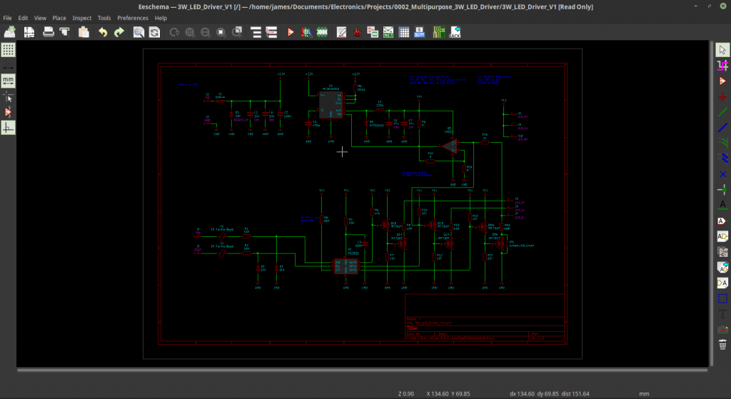
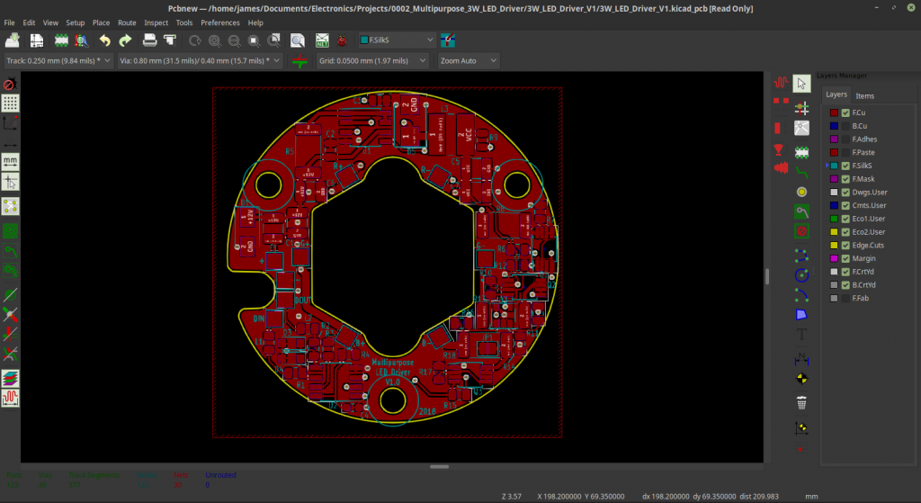
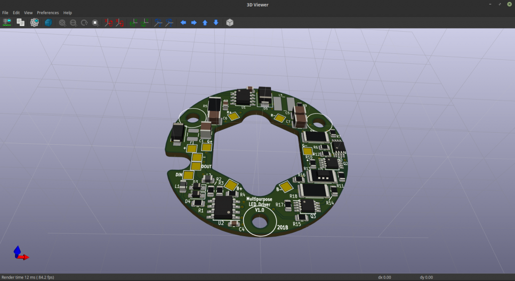
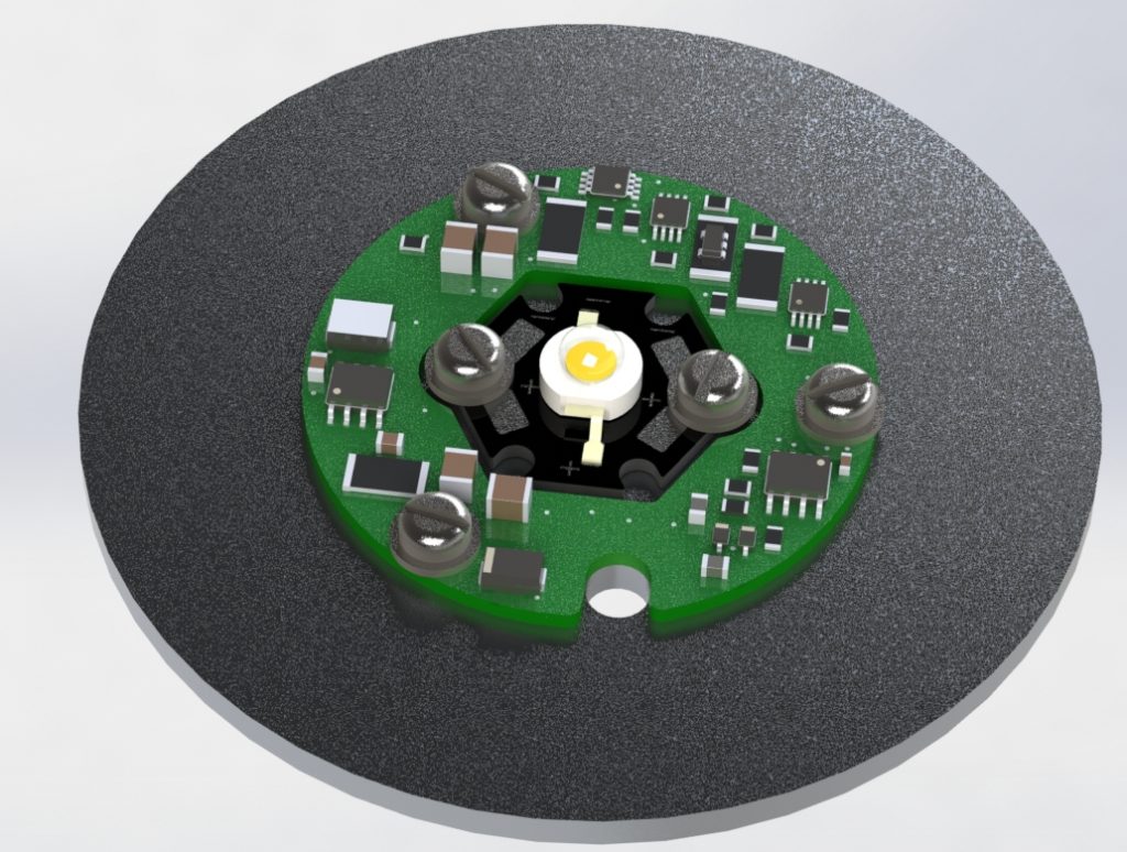
So with this list, I designed a PCB to fit round the outside of a 3W Star-type LED. It can be configured into either an RGB driver or a single colour driver by what is populated on the board. I think pictures will show more than words here!
Now I just have to order the parts and the boards!